Beginner Project toggle IO pins

BEGINNER PROJECT: ShastaPlus IO Pin Toggle

IMG_5555_copy

Objective: learn to toggle 1 pc board IO pin, then expand to 8 pins, and drive LEDs. All pins used here are called “User FPGA pins”.

As a beginner I used the Wf_Blinky.v example, online research, and Support Forum help (thank you). Although this project is a “trivial” use of an FPGA, I just wanted to get anything at all to work.

A 16 MHz crystal, external to the FPGA, is the clock source. A 28 bit register (bits 0 - 27) is incremented or decremented, depending on LED wiring, to get a slower count in the higher bits. Bit 24 could be the typical Hello World as it toggles once per second.

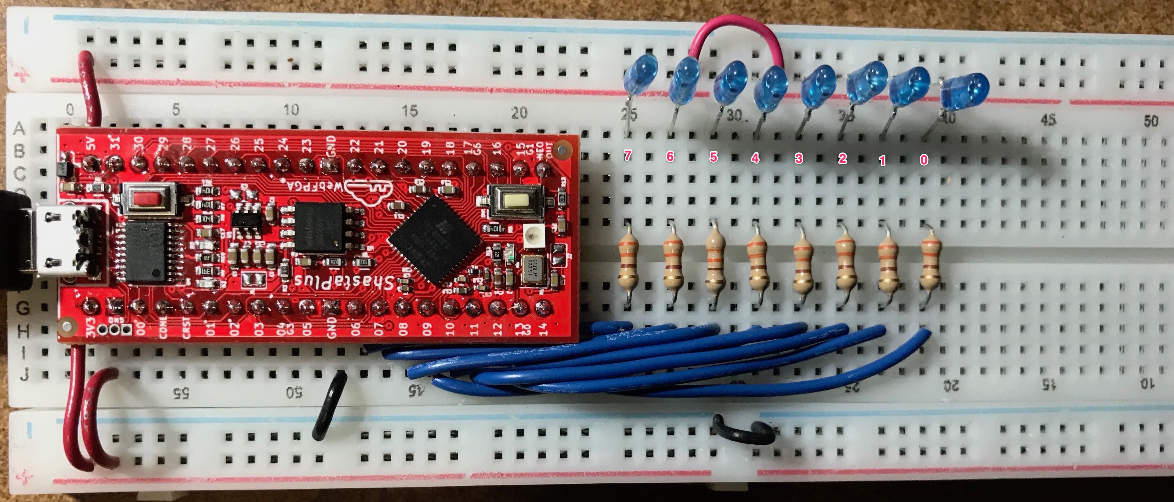
The upper 8 counter register bits are routed to pc board pins using @MAP (note the capitalization, I did not at first and nothing worked). Those IO pins are connected to 330Ω current limiting resistors which then connect to blue LED cathodes. The LED anodes connect to the 3.3 volt rail. A LOW or 0 in the corresponding counter register bit will turn a LED ON.

In order to have a LED counter which visually counts up, the counter register must be decremented. On power up the pins seem to all be HIGH (0xFFF FFFF). After the first decrement the counter is 0xFFF FFFE so bit 0 is LOW. If an LED were connected there, it would turn on and off too quickly to see.

Once the decrementing gets to 0xFEF FFFF (1111 1110 1111 1111 1111 1111 1111), bit 20 is LOW so LED_0 turns on, but briefly, for about 1/16 second.

When the count is 0xEFF FFFF (1110 1111 1111 1111 1111 1111 1111), that LOW in bit 24 turns on LED_4, for about 1 second.

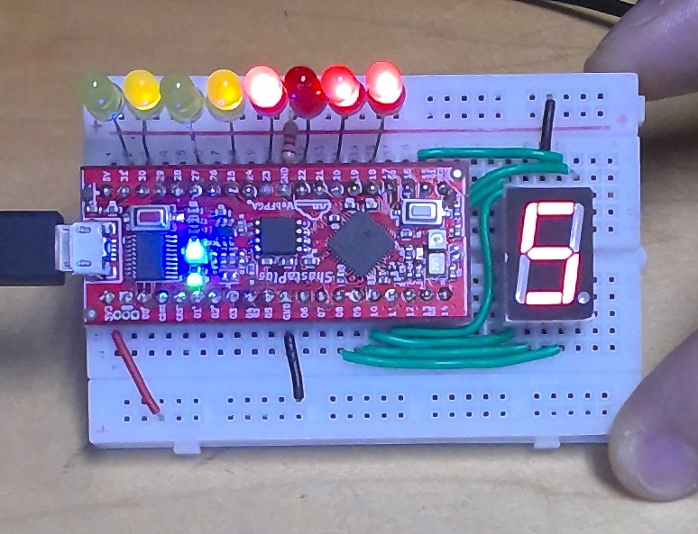
The LEDs do work reversed, with their cathodes connected to ground and the anodes connected to the current limiting resistors. To get a visual up-counter, the FPGA counter register needs to be incremented. However, all LEDs are slightly glowing at power up and during flashing, unlike with the other wiring.

In either case the 8 LEDs draw little current, maybe 2 mA per LED. Each blue LED had a measured voltage drop of about 2.7 volts and each resistor about .55 volt
(.55V / 330 ~ 1.7 mA). With all 8 LEDs on the current draw from them would be about 16 mA. Even with such a low current through them, the blue LEDs are quite bright in a fully lit room.

// Toggle one pc board pin for Hello World LED
// rr Sept 1, 2019
// pc board pin 6 connects to 330 ohm resistor which 
// connects to LED cathode, LED anode to 3.3 volt rail.
// LED will toggle about once per second

// @MAP_IO LED_0 06

 module fpga_top(output wire LED_0, input wire WF_CLK);

    reg [27:0] counter; 
    reg state0;
    assign LED_0 = state0; 
  
    always @ (posedge WF_CLK) begin
        counter  <= counter - `b1;
        state0 <= counter[24];  
    end
endmodule
Summary

This text will be hidden

**// ShastaPlus 8 pin toggle, rr Sept 1, 2019**
// PC board pins 06, 07, 08, 09 10, 11, 12, 14 to 330Ω resistors,
// other end of resistors to LED cathodes, LED anodes to 3.3V rail.
// Counter register decrements and rolls over, driven by 16 MHz
// crystal. LEDs show the highest 8 bits in counter register.
// LED_7 toggles slowest; LED_4 toggles about once per second.

// @MAP_IO LED_7 06
// @MAP_IO LED_6 07
// @MAP_IO LED_5 08
// @MAP_IO LED_4 09
// @MAP_IO LED_3 10
// @MAP_IO LED_2 11
// @MAP_IO LED_1 12
// @MAP_IO LED_0 14

module fpga_top(output wire LED_0, output wire LED_1,
    output wire LED_2, output wire LED_3, output wire LED_4,
    output wire LED_5, output wire LED_6, output wire LED_7,
    input wire WF_CLK);

    reg [27:0] counter;
    reg state0; reg state1; reg state2; reg state3;
    reg state4; reg state5; reg state6; reg state7;

    assign LED_0 = state0; assign LED_1 = state1;
    assign LED_2 = state2; assign LED_3 = state3;
    assign LED_4 = state4; assign LED_5 = state5;
    assign LED_6 = state6; assign LED_7 = state7;

    always @ (posedge WF_CLK) begin
        counter  <= counter - `b1;
        state0 <= counter[20];
        state1 <= counter[21];
        state2 <= counter[22];
        state3 <= counter[23];
        state4 <= counter[24];
        state5 <= counter[25];
        state6 <= counter[26];
        state7 <= counter[27];
    end
endmodule

Short video clip at: https://www.youtube.com/watch?v=Y3zgIjvGK8E

Hi robr,

A nice demo, but you state that the anodes connect to the 3.3V – it looks to me that they are connected to +5V. Since the FPGA inputs are not 5V tolerant that might explain:

You should avoid connecting 5V signals to the FPGA I/O pins. The iCE40 UltraPlus data sheet states that the maximum input voltage applied is 3.6V. (Table 4.1 Absolute Maximum Ratings)

Also, you have more like 7mA through each LED (5V - 2.7V)/330 Ohm, not 2mA. Did you actually measure 0.55V across the current limiting LEDs or is that a [mis] calculated value using 3.3V not 5V source?

David

Hi dabrams,

Fortunately, I still have the breadboard wired up. The picture looks like the upper plus rail is coming from the ShastaPlus 5V. But it isn’t. That red wire goes under the board and connects to the bottom red rail which is driven by the ShastaPlus 3.3V.

It never occurred to me that I need to be more careful when taking a picture like this one.
Thank you for your reply, I am glad to know about this.

I remeasured the voltage drop across the LED limiting resistors. However, I had replaced the 330 ohm with 2.2k ohm. A couple of these resistors measured 2170 ohms.

The voltage drop across that resistor with the LED ON was .76 volt so the LED current was approximately .76/2170 = .00035 or about .35 mA. The LEDs are still visible in a bright room and easily seen although they do look sort of “dim-ish”.

I put one resistor plus LED and drove it from the rails, unconnected to any FPGA pin. This measured .81/2170 = .00037. The voltage drop across the LED measured 2.49V.

2.49V + .81V = 3.3V. The rail from the ShastaPlus measured 3.3V. All measurements were made with a Keysight U1273A meter.

So it looks to me like those particular blue LEDs are incredibly efficient in making visible light, at almost no drive at all.

Again, thank you for the reply. I will be more careful next time I post a picture.

Robert

Robert,

Thanks for letting me know. Sorry I misinterpreted the picture. Then I don’t know why you are seeing the LEDs lighting up when they should be off. That is odd. (I thought you might have current flow through the LED from +5V through a FPGA port protection diode to Vcc.)

330 ohm should be fine when driven from 3.3V. 2mA is a reasonable current for high efficiency LEDs. The port pins are good for +/-8mA.

I’m new to FPGA design and I was working on something similar to get my first test going. I thought I’d share this in case others might be interested in seeing a similar approach. This is just creating a counter and capturing the binary output and displaying it via LEDs and mapping those using Verilog into a 7-Segment display.

// 8 Bit Binary Counter LED Display 
//
// @MAP_IO LED0 31  
// @MAP_IO LED1 30
// @MAP_IO LED2 27  
// @MAP_IO LED3 25  
// @MAP_IO LED4 23  
// @MAP_IO LED5 22  
// @MAP_IO LED6 20  
// @MAP_IO LED7 18  

// @MAP_IO RESET 1  
// @MAP_IO LEDA 15  
// @MAP_IO LEDB 19
// @MAP_IO LEDC 8  
// @MAP_IO LEDD 9  
// @MAP_IO LEDE 10  
// @MAP_IO LEDF 11  
// @MAP_IO LEDG 21  
// @MAP_IO LEDdot 14

module fpga_top(
		input WF_CLK,
		
		output reg LED0,
        output reg LED1,
	    output reg LED2,
	    output reg LED3,
	    output reg LED4,
	    output reg LED5,
	    output reg LED6,
	    output reg LED7,
		
		output LEDA,
		output LEDB,
		output LEDC,
		output LEDD,
		output LEDE,
		output LEDF,
		output LEDG
	);
	
	reg [31:0] cnt;
	reg [3:0] counter;
	reg [6:0] seg_data;
	
	reg [31:0] pinIndex = 21; 		// Practical min is 20, max 25.

	always @(posedge WF_CLK) 
		begin
		
		    cnt <= cnt + 'b1;                              // Increment the 32-bit counter
		    counter <= {LED0, LED1, LED2, LED3};           // Pick the top 4 LEDs to display on the 7-segment display
		    
		    LED0 <= cnt[pinIndex + 7];                      // I'm using a reg here so I can easily
		    LED1 <= cnt[pinIndex + 6];                      // adjust which bits of the counter to 
		    LED2 <= cnt[pinIndex + 5];                      // base my binary and 7-segment display  
		    LED3 <= cnt[pinIndex + 4];                      // on. Increase the index to speed the       
		    LED4 <= cnt[pinIndex + 3];                      // counter up, decrease it to slow it down.
		    LED5 <= cnt[pinIndex + 2];                      // Your not actually changing the speed of 
		    LED6 <= cnt[pinIndex + 1];                      // the counter, just using a different 
		    LED7 <= cnt[pinIndex];			                // set of 8-bits from the counter. Each 
		end                                                 // index value adjusts the speed by 2x. 
                                                            // This is because the counter is binary, base-2.        
	always @(*)
		case (counter)       // abcdefg             // 7-Segment display bit to pin mappings
			4'b0000:seg_data=7'b1111110; // 0       // Binary counters count from 0 to 15.
			4'b0001:seg_data=7'b0110000; // 1       // This case statement takes the 4-bit
			4'b0010:seg_data=7'b1101101; // 2       // binary value and translates it to 
			4'b0011:seg_data=7'b1111001; // 3       // an 8-bit binary value to control 
			4'b0100:seg_data=7'b0110011; // 4       // which LEDs on the 7-segement display 
			4'b0101:seg_data=7'b1011011; // 5       // are turned high. The 8-bit number is 
			4'b0110:seg_data=7'b1011111; // 6       // not what we are interested in, but
			4'b0111:seg_data=7'b1110000; // 7       // each bit corresponds to an LED on 
			4'b1000:seg_data=7'b1111111; // 8       // the 7-segment display. 
			4'b1001:seg_data=7'b1111011; // 9       
			4'b1010:seg_data=7'b1111110; // 10      
			4'b1011:seg_data=7'b0110000; // 11       
			4'b1100:seg_data=7'b1101101; // 12       
			4'b1101:seg_data=7'b1111001; // 13       
			4'b1110:seg_data=7'b0110011; // 14      
			4'b1111:seg_data=7'b1011011; // 15      
		endcase                                                               
	 
	assign LEDA = seg_data[6];                      // Continuous assign each bit position 
	assign LEDB = seg_data[5];                      // from the 8-bit binary reg seg_data
	assign LEDC = seg_data[4];                      // to the output pins on the ShastaPlus
	assign LEDD = seg_data[3];                      // board, which maps to the 7-segment
	assign LEDE = seg_data[2];                      // LED a-g segments. This will create 
	assign LEDF = seg_data[1];                      // a connection from the register 
	assign LEDG = seg_data[0];                      // directly to the output PIN, which 
	                                                // means it will immediately display
	                                                // the value any time the register
endmodule                                           // is updated.

Here’s a picture of my setup. I cheated a bit by using a single resistor on the ground. So the more LEDs that are on, they will all dim. If you don’t like that, go with the correct approach to using a resister per LED. But it seems fine to save space for a demo like this.

The point of this is was to work through using a binary counter and displaying it on a 7-Seg display. This is basically what a counter and 7-Segment display driver is able to do. But with Verilog, you can just code it all yourself.

The next step is to add a second display and map the first four LEDs to display 1 and the second set of four to display 2, which gives you a two-digit BCD display. Converting the binary to decimal will give you a typical counter and decimal display. My final test will be to add a shift register (or two) to drive four 7-seg displays, similar to how the kits 7-Seg display board is functioning.

Thank you for posting your project. I wanted to examine your code and learn and respond earlier. But too many things got in the way. I still find it incredibly hard to learn this type of programming, but I might put in some effort next year.