Documentation for the microcontroller?

Is there any chance of getting some documentation on the on-board microcontroller - what commands it responds to via USB, and how one might use it to interact with the FPGA?

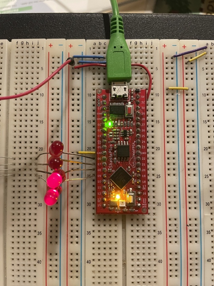
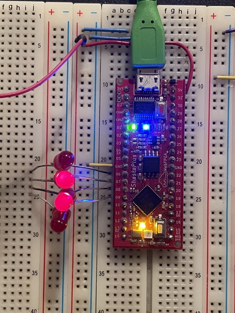
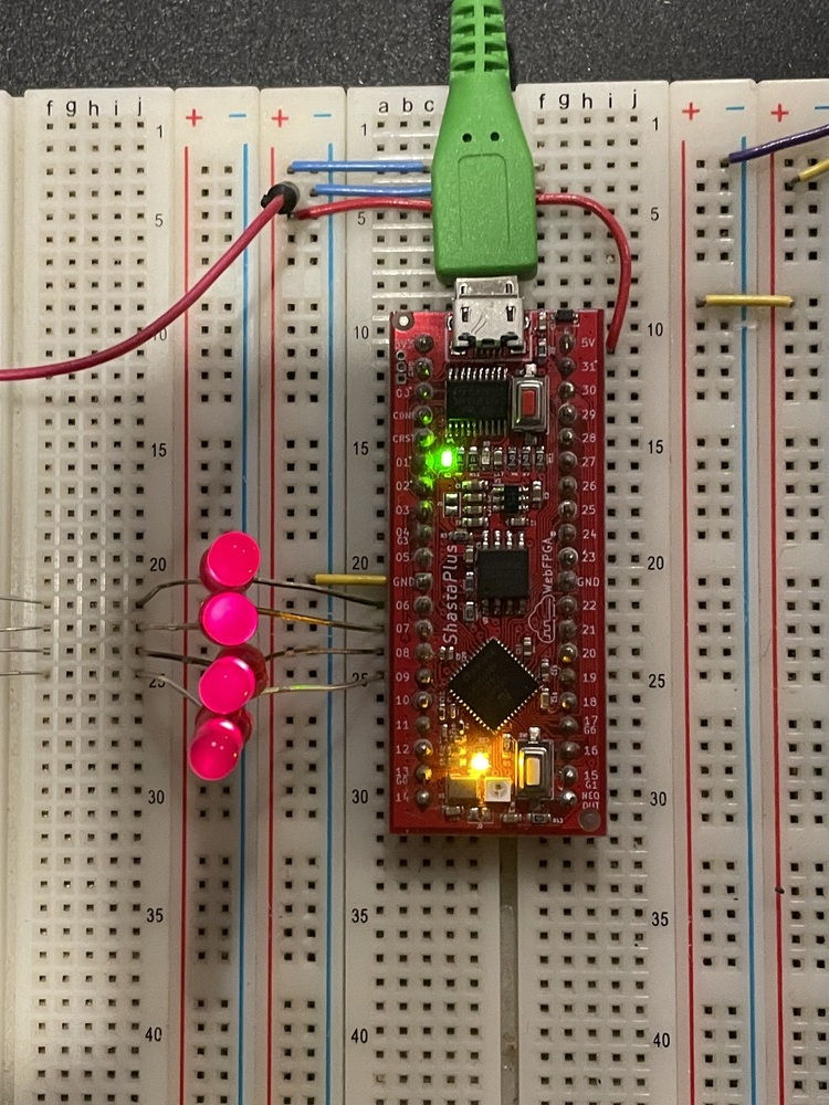
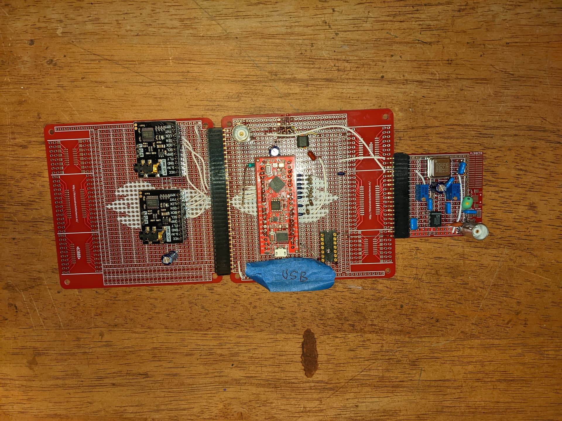
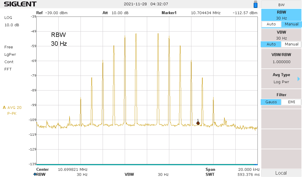
My reason for asking: I’m quite well along in my project, and I have my Shasta board generating 10.7 MHz frequency-modulated RF test signals (multiplex-stereo, for calibrating FM tuners). I’d like to be able to use USB, and the microcontroller interface, as a way of interacting with and reconfiguring the running gateware program (as opposed to having to recompile and flash a modified gateware).

If there’s some reasonable way to get the micro to talk to the FPGA via a serial protocol (SPI or UART-style) I could write the corresponding FPGA logic. Lacking knowledge of what the micro can do, I can’t.

I recall that there was some intention to open-source more of the development toolkit (in particular, the bitstream compression program) - that also would be nice!

Hi Dave,

We just read your post and wanted to acknowledge that we saw it.

We’ll follow up later this week with a more detailed response regarding the open source toolchain + bitstream compression/decompression code.


But briefly…

There are four pins hardwired between the MCU and FPGA. Our software allows you to instruct the MCU to set the pin states. Right now, this is only supported on the webpage (no other users actually requested this feature via the CLI tools… but we are happy to support it).

https://book.webfpga.io/#appendix-a--fpga-board-pinouts
(Look at the blue oval pin definitions in the link above.)

Example code:

module fpga_top(
    input wire WF_CPU1,
    input wire WF_CPU2,
    input wire WF_CPU3,
    input wire WF_CPU4
);

Right now, you will have to use the Web IDE to toggle the pins. We will follow up with a method that CLI-only. Then, you can come up with a simple bit-bang protocol to configure your hardware. We just need to publish some additional Python control code on our side.

– Ryan and Mick

@DavePlatt

Hi Dave, we just pushed some code to the Python utility to set the MCU->FPGA bits.

This will allow you to communicate to the FPGA. You can send your configuration over this USB channel.

Here is an example with photos. The Verilog source:

// @MAP_IO b0 6
// @MAP_IO b1 7
// @MAP_IO b2 8
// @MAP_IO b3 9

module fpga_top(
    input  wire WF_CPU1,
    input  wire WF_CPU2,
    input  wire WF_CPU3,
    input  wire WF_CPU4,
    
    output wire b0,
    output wire b1,
    output wire b2,
    output wire b3
);

// The LEDs are active low. We are sinking current through the FPGA.
assign b0 = ~WF_CPU1;
assign b1 = ~WF_CPU2;
assign b2 = ~WF_CPU3;
assign b3 = ~WF_CPU4;

endmodule

Once that code is flashed, you can use the website to toggle bits – or use the command line tool.

Grab the latest tool with: “pip install webfpga==0.4.0”.

  ---
  BITSTRING can be a 4-character string of '0', '1', or 'X'. BITSTRING can
  also be 'init'.

  If the device has just powered on, you need to run `webfpga setbits init`.
  ---

  Examples:
   $ pip install webfpga==0.4.0
    webfpga setbits init    # Initialize CPU->FPGA communication.
    webfpga setbits 0000    # Set all bits to 0.

    webfpga setbits 0011    # Set the first two bits to 0, last two bits to 1.
    webfpga setbits 1XXX    # Set first bit to 1.
    webfpga setbits X000    # Set last three bits to 0.

webfpga setbits 0000

webfpga setbits 0011

webfpga setbits X110

webfpga setbits 1111


ADDITIONAL NOTES

  • Makes sure to run “webfpga setbits init” before sending bitstrings. The MCU needs to be properly initialized. All bits will toggle during the “webfpga setbits init” command.

    • (Note: This isn’t required on the Web IDE.)
  • The protocol can execute every 1 millisecond. We are going to publish some additional Verilog / Python code to communicate bytes. It should be pretty simple to shift in ASCII characters, etc.

  • Also, the compression code is located here: webfpga/cli – Compress.py

  • The repository contains other implementation details. You can look at the source here: github.com/webfpga/cli

After installing the webfpga Python package, you can also script with Python:

#!/usr/bin/env python3

from webfpga.Utilities import *

dev = get_device()
init_bits(dev)

# bitstring: 0110
set_bit(dev, 0, 0)
set_bit(dev, 1, 1)
set_bit(dev, 2, 1)
set_bit(dev, 3, 0)

Thanks, Ryan! This will all be very useful.

For your amusement: I’ve attached a slightly-out-of-date photo of my current signal-generator prototype board set, with the Shasta at the center of all of the action. It feeds a pair of I2S stereo audio DAC boards on the left (for baseband audio test signal output). Just to the right of the Shasta you can see the resistors which make up a simple 8-bit R-2R DAC, which feeds into a funky little low-pass filter along the upper part of the board, and then over to an RF upconverter board on the right (since replaced by a different design).

The lower image is an RF spectrum analyzer screen-shot, showing the 10.7 MHz signal coming out of the R-2R DAC and low-pass filter. The Shasta is using 60 MHz direct digital synthesis to create this signal - it’s a carrier at 10.7 MHz, frequency-modulated by a 1 kHz sinewave, with a peak deviation of 2405 Hz. This creates a spectrum where the intensity of the 10.7 MHz carrier drops to zero, and all of the signal power is carried on FM sidebands positioned 1 kHz apart.

This afternoon I got the new double-balanced-mixer upconverter board working (somewhat) and was able to see this spectrum shifted up to the FM band at 89.3 MHz and 110.7 MHz.

If I switch to a slightly more complex baseband-signal configuration, the board creates an FM stereo composite signal which means “stereo signal, 1000 Hz in the left channel, 440 Hz in the right” and then feeds that into the DDS as the modulating signal (75 kHz peak deviation). If I inject the 10.7 MHz result into a stereo tuner’s IF path, the STEREO light comes on and I hear those two tones, just as intended.

I’m really glad you guys decided to put together this board - it was the perfect tool for the learning and development I wanted to do. Thank you again!